Embedded Figures and Figure Completion
1. What this chapter tests
These visual-reasoning problems test whether you can separate a useful shape from distracting strokes and reconstruct a missing part using a stated rule. Work from visible geometry rather than guessing what an object resembles.
| Task | What must be found | Main check |
|---|---|---|
| Embedded figure | The complete target inside a larger drawing | Every target stroke and junction is present |
| Figure completion | A missing part of a given drawing | Boundaries and the stated pattern rule agree |
| Symmetry completion | The piece required by one or more reflection axes | Corresponding points are equally far from the axis |
| Line continuation | The hidden section of straight or curved paths | Entry, exit and direction remain consistent |
In an embedded-figure problem, extra lines in the larger figure are normally permitted. In a completion problem, extra lines in a proposed tile can make it wrong. Always read the exact instruction.
2. How to use the diagrams
The top drawing is target T or the incomplete figure. The four lower panels are options A–D. Panel borders and dashed guides are aids to layout, not strokes that may be used to build the answer. Compare actual dark strokes only. In the solutions, green strokes identify a match or fill a gap.
The first practice family uses a hidden unit grid with equally spaced vertices. Coordinates in explanations begin at the top-left of each option: x increases to the right and y downward. They provide a precise way to verify a trace; you do not need to calculate coordinates to solve visually.
3. Translation, rotation and reflection
Translation moves the whole target without changing its orientation or size. Rotation turns it about a point. Reflection reverses its handedness across a mirror line. These operations are different permissions.
- If rotation is forbidden, a right-facing hook cannot become a downward-facing hook.
- If rotation through multiples of 90° is allowed, try 0°, 90°, 180° and 270°.
- Rotation permission does not automatically permit a mirror image.
- If resizing is forbidden, preserve the relative and absolute segment lengths shown on the common grid.
- If an exam supplies its own orientation rule, use that rule. Do not assume a universal convention for every publisher.
For example, a path that moves right, down, then right retains that turn sequence when translated. A mirrored path changes handedness. An asymmetric shape is a better anchor than a square because a square can conceal an orientation error.
4. A reliable embedded-figure method
- Identify one distinctive feature: a long arm, a three-way branch, an unequal pair of sides, or a sequence of two bends.
- Locate a possible copy of that feature in an option.
- Trace the connected target from that anchor without lifting your imagined pen across a missing stroke.
- Compare the direction and length of each next segment.
- Check the remaining branches or disconnected components in their correct relative positions.
- Reject the option as soon as one required piece is absent.
- Confirm the complete target in the surviving option.
Do not merely count lines. Two figures with six strokes can have different connections. Do not build half the target in one area and the other half elsewhere unless the target itself has those disconnected components in exactly that relationship.
5. Crossings, junctions and distracting extensions
A target endpoint may lie on a longer line in the candidate; an added extension does not erase the target. Similarly, an extra line may cross a required stroke. You may ignore the extra line when the target is still present.
However, a visible gap cannot be bridged mentally. A crossing is not evidence that the line bends there. Follow the actual target's geometry. In this chapter, each embedded target is made of connected horizontal and vertical unit strokes. Longer displayed runs can contain several such strokes. Only strokes in the drawing count; box borders are excluded.
Fast rejection checks: a necessary vertical arm is missing; a bend turns the wrong way; the long side is too short; a branch appears at the wrong distance; only a reflected copy exists when reflection is forbidden.
6. Embedded figures with permitted rotation
Use the same tracing method, but fix one orientation at a time. Mentally rotate the entire target, not individual arms independently. After choosing an orientation, all lengths, bends and branches must agree together.
For a local coordinate point (x,y), a quarter-turn can be represented by (-y,x), followed by a translation to place it in the option. This is an optional checking device. Rotating every point of a figure by the same transformation preserves distances and connections; rotating only one branch changes the figure.
A frequent hard-level trap is an option with the correct number of corners but the wrong order of clockwise and anticlockwise turns. Trace from the same endpoint to compare fairly.
7. Figure completion: start at the boundary
Inspect where each visible stroke meets the empty region. Note its position, direction, thickness and any stated colour or shading rule. Then examine the candidate edges before its attractive central design.
A piece that joins at one boundary but creates a jump at another is wrong. A matching number of strokes is only a preliminary check. In a general completion question, continuity alone may not determine a unique answer; a symmetry or repetition rule may also be supplied. Use all the stated constraints rather than inventing a rule.
8. One-axis and two-axis symmetry
With a vertical symmetry axis, left and right exchange places while height stays the same. With a horizontal axis, top and bottom exchange places while horizontal position stays the same.
If a square must be symmetric about both centre lines and its bottom-right quadrant is missing:
- Reflect the top-right quadrant across the horizontal centre line.
- Independently reflect the bottom-left quadrant across the vertical centre line.
- Both constructions must give the same piece.
- Equivalently, rotate the top-left quadrant by 180° about the centre of the full square.
Do not place an unchanged copy of the top-left tile into the gap. That works only for special shapes with the relevant internal symmetry. Our options include plausible one-axis and unchanged-copy distractors.
9. Straight-line continuation
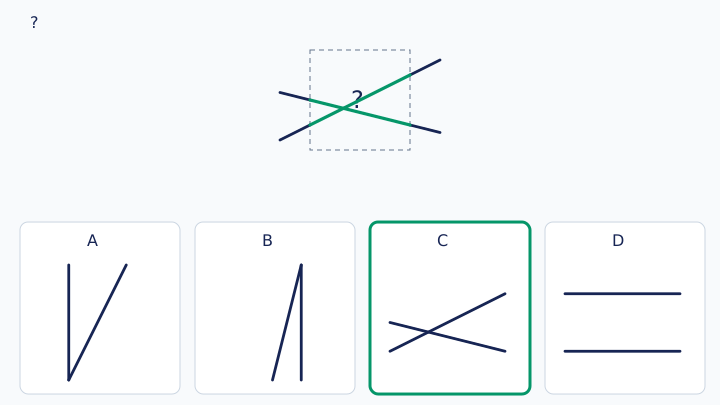
A straight stroke keeps the same direction through a covered area. Extend the outside fragments using an imaginary ruler. Check that the opposite fragment lies on the same straight line.
Suppose a line enters the left edge of a tile at (0,1) and exits its right edge at (4,3). It slopes downward to the right in the displayed coordinate system. A horizontal segment from (0,1) to (4,1) shares the entry point but fails the exit and slope tests.
When lines cross inside a missing piece, continue each original line straight through the crossing. Do not switch onto the other line. All relevant fragments must be accounted for and no additional stroke may be introduced when the question forbids it.
10. Curves, shading and repeated motifs
Other examinations may use arcs, circles, shaded sectors, dots or repeating ornaments. Check the local tangent of a curve at the edge, the centre and radius of an arc, and the orientation of shaded regions. A curved piece can join at the right endpoint while bending the wrong way.
For repeated motifs, compare spacing as well as shape. If shading alternates, verify the alternation across the boundary of the missing tile. Do not assume symmetry solely because the figure looks decorative. The 80 online questions here focus on exact straight-stroke embedding, two-axis symmetry and straight-line continuity; use these principles when practising curved and shaded variants elsewhere.
11. Distinguish this topic from related chapters
| Related topic | Difference |
|---|---|
| Mirror image | Transform the entire given figure by reflection |
| Paper folding | Track reflections caused by physical folds |
| Figure series | Infer a rule across successive complete figures |
| Counting figures | Count all qualifying shapes rather than locate one target |
| Embedded figure | Find an existing copy inside additional strokes |
| Figure completion | Supply a missing part that satisfies the constraints |
12. Typical mistakes and corrections
| Mistake | Correction |
|---|---|
| Choosing by overall appearance | Verify each required stroke |
| Allowing rotation without permission | Read the orientation instruction first |
| Confusing rotation with reflection | Follow an asymmetric bend sequence |
| Ignoring a small branch | Mark every target component mentally |
| Using the option panel border | Ignore layout frames and dashed guides |
| Checking just one symmetry axis | Construct the answer independently from both adjacent tiles |
| Counting lines without checking endpoints | Match position, direction and connectivity |
| Choosing an unnecessarily complex rule | Prefer the explicitly stated rule |
13. A practical exam routine
Read permissions → identify the anchor or gap boundaries → eliminate definite mismatches → trace the entire surviving figure → confirm the option letter. If two options appear valid, recheck whether you accidentally used a panel border, reflected the target or ignored an extra stroke in a completion tile.
Practise slowly before adding a timer. Record the type of mistake, not just the score. After solving a question, explain which exact stroke disqualifies each distractor. On a small screen, enlarge the diagram so that short gaps are visible.
14. Revision and practice plan
Embedding checklist: full target, correct orientation, correct lengths, correct branches, no imagined gaps. Completion checklist: all boundaries, correct axes, line directions, no missing or forbidden extra strokes.
The online bank contains 80 illustrated questions: 20 fixed-orientation embeddings, 20 rotation-permitted embeddings, 20 two-axis symmetry completions and 20 straight-line completions. Four focused tests contain 20 questions each; the complete practice test contains all 80. The following 30 exercises sample all four groups. Attempt them before opening the answer section.
15. Illustrated practice
Practice 01
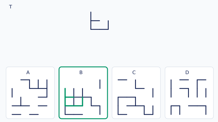
Which option contains every stroke of target T? Extra lines are allowed. Keep the target upright: translation only; no rotation, reflection or resizing.
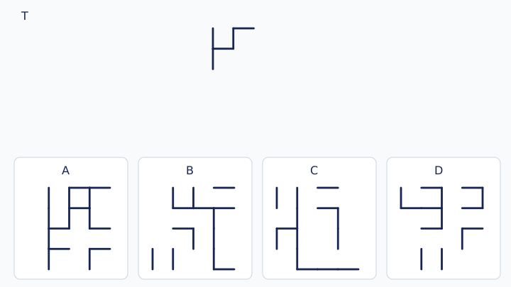
A: Figure A · B: Figure B · C: Figure C · D: Figure D
Practice 02
Which option contains every stroke of target T? Extra lines are allowed. Keep the target upright: translation only; no rotation, reflection or resizing.
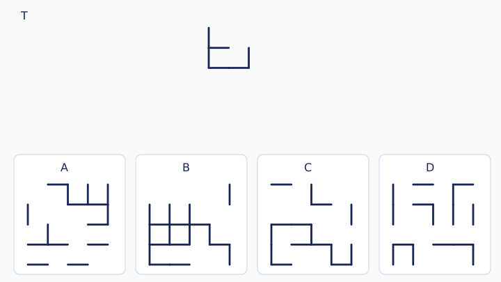
A: Figure A · B: Figure B · C: Figure C · D: Figure D
Practice 03
Which option contains every stroke of target T? Extra lines are allowed. Keep the target upright: translation only; no rotation, reflection or resizing.
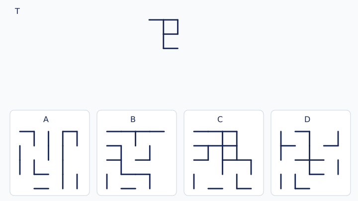
A: Figure A · B: Figure B · C: Figure C · D: Figure D
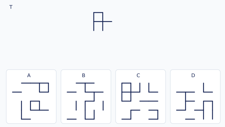
Practice 04
Which option contains every stroke of target T? Extra lines are allowed. Keep the target upright: translation only; no rotation, reflection or resizing.
A: Figure A · B: Figure B · C: Figure C · D: Figure D
Practice 05
Which option contains every stroke of target T? Extra lines are allowed. Keep the target upright: translation only; no rotation, reflection or resizing.
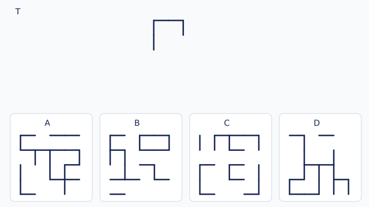
A: Figure A · B: Figure B · C: Figure C · D: Figure D
Practice 06
Which option contains every stroke of target T? Extra lines are allowed. Keep the target upright: translation only; no rotation, reflection or resizing.
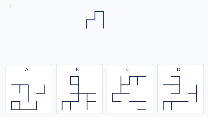
A: Figure A · B: Figure B · C: Figure C · D: Figure D
Practice 07
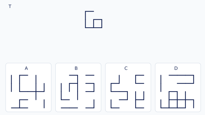
Which option contains every stroke of target T? Extra lines are allowed. Keep the target upright: translation only; no rotation, reflection or resizing.
A: Figure A · B: Figure B · C: Figure C · D: Figure D
Practice 08
Which option contains every stroke of target T? Extra lines are allowed. Keep the target upright: translation only; no rotation, reflection or resizing.
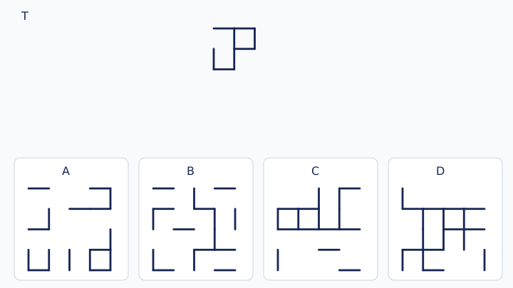
A: Figure A · B: Figure B · C: Figure C · D: Figure D
Practice 09
Which option contains every stroke of target T? Extra lines are allowed. Rotation by a multiple of 90° is allowed; reflection and resizing are not.
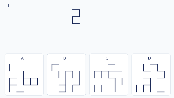
A: Figure A · B: Figure B · C: Figure C · D: Figure D
Practice 10
Which option contains every stroke of target T? Extra lines are allowed. Rotation by a multiple of 90° is allowed; reflection and resizing are not.
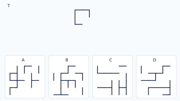
A: Figure A · B: Figure B · C: Figure C · D: Figure D
Practice 11
Which option contains every stroke of target T? Extra lines are allowed. Rotation by a multiple of 90° is allowed; reflection and resizing are not.
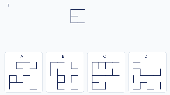
A: Figure A · B: Figure B · C: Figure C · D: Figure D
Practice 12
Which option contains every stroke of target T? Extra lines are allowed. Rotation by a multiple of 90° is allowed; reflection and resizing are not.
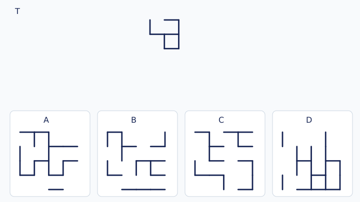
A: Figure A · B: Figure B · C: Figure C · D: Figure D
Practice 13
Which option contains every stroke of target T? Extra lines are allowed. Rotation by a multiple of 90° is allowed; reflection and resizing are not.
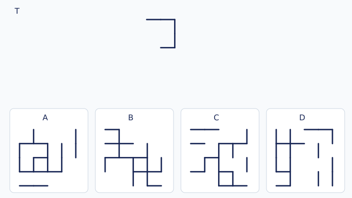
A: Figure A · B: Figure B · C: Figure C · D: Figure D
Practice 14
Which option contains every stroke of target T? Extra lines are allowed. Rotation by a multiple of 90° is allowed; reflection and resizing are not.
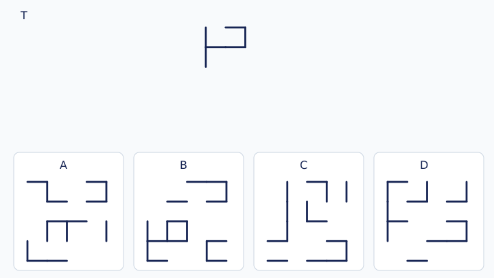
A: Figure A · B: Figure B · C: Figure C · D: Figure D
Practice 15
Which option contains every stroke of target T? Extra lines are allowed. Rotation by a multiple of 90° is allowed; reflection and resizing are not.
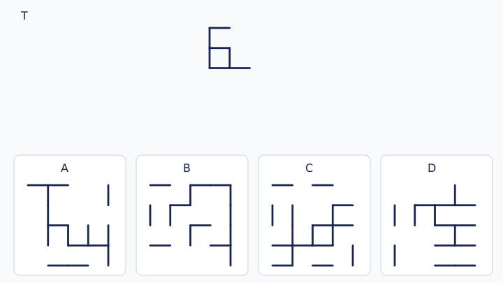
A: Figure A · B: Figure B · C: Figure C · D: Figure D
Practice 16
Which option contains every stroke of target T? Extra lines are allowed. Rotation by a multiple of 90° is allowed; reflection and resizing are not.
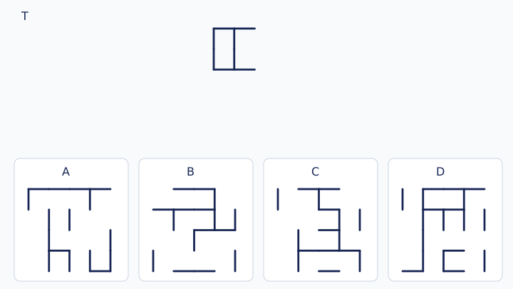
A: Figure A · B: Figure B · C: Figure C · D: Figure D
Practice 17
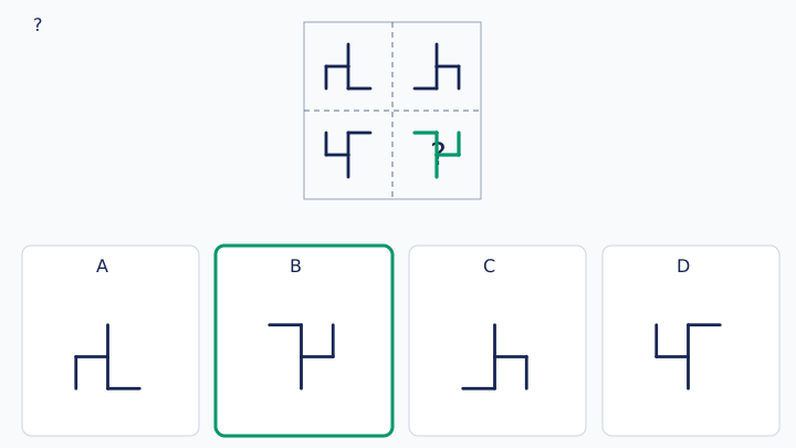
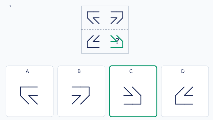
The complete square must be symmetric about BOTH dashed centre lines. Which tile fills the missing bottom-right quadrant? Place each option upright, without rotating it.
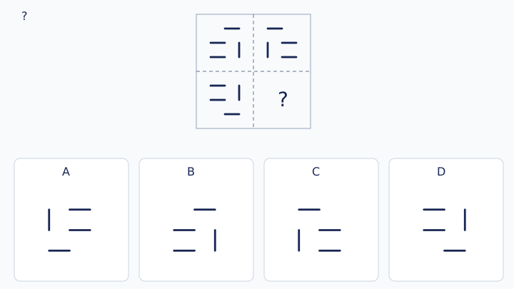
A: Figure A · B: Figure B · C: Figure C · D: Figure D
Practice 18
The complete square must be symmetric about BOTH dashed centre lines. Which tile fills the missing bottom-right quadrant? Place each option upright, without rotating it.
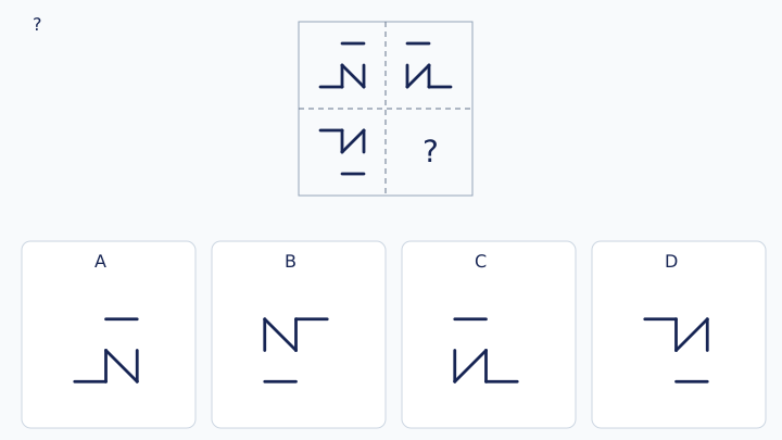
A: Figure A · B: Figure B · C: Figure C · D: Figure D
Practice 19
The complete square must be symmetric about BOTH dashed centre lines. Which tile fills the missing bottom-right quadrant? Place each option upright, without rotating it.
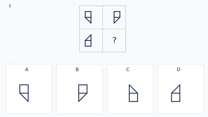
A: Figure A · B: Figure B · C: Figure C · D: Figure D
Practice 20
The complete square must be symmetric about BOTH dashed centre lines. Which tile fills the missing bottom-right quadrant? Place each option upright, without rotating it.
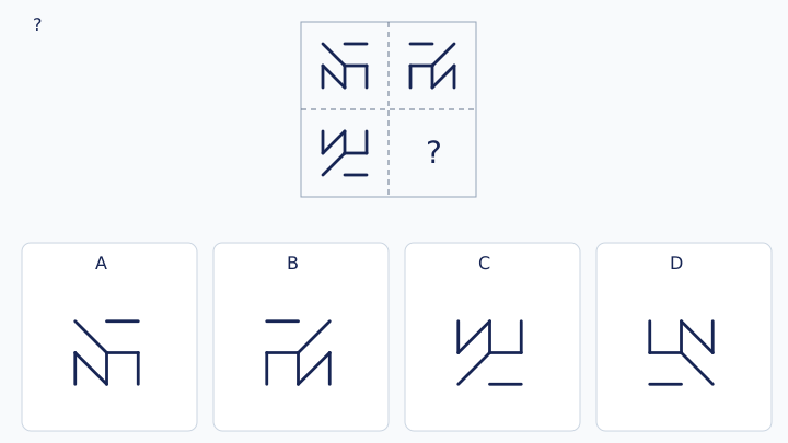
A: Figure A · B: Figure B · C: Figure C · D: Figure D
Practice 21
The complete square must be symmetric about BOTH dashed centre lines. Which tile fills the missing bottom-right quadrant? Place each option upright, without rotating it.
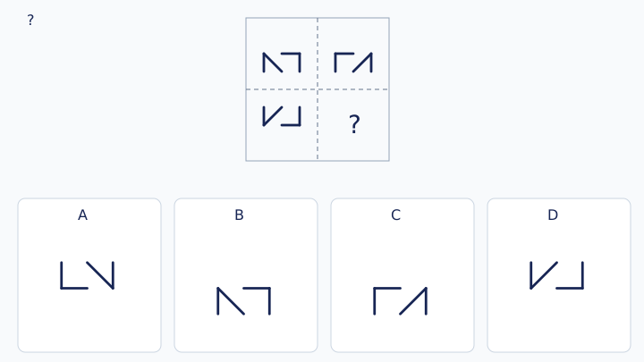
A: Figure A · B: Figure B · C: Figure C · D: Figure D
Practice 22
The complete square must be symmetric about BOTH dashed centre lines. Which tile fills the missing bottom-right quadrant? Place each option upright, without rotating it.
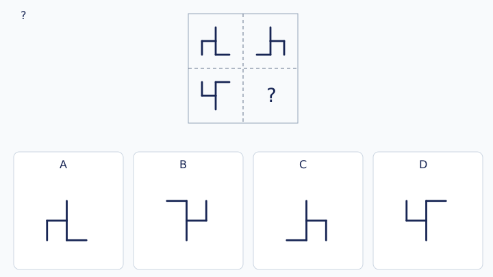
A: Figure A · B: Figure B · C: Figure C · D: Figure D
Practice 23
The complete square must be symmetric about BOTH dashed centre lines. Which tile fills the missing bottom-right quadrant? Place each option upright, without rotating it.
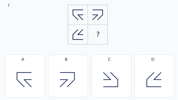
A: Figure A · B: Figure B · C: Figure C · D: Figure D
Practice 24
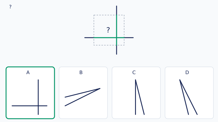
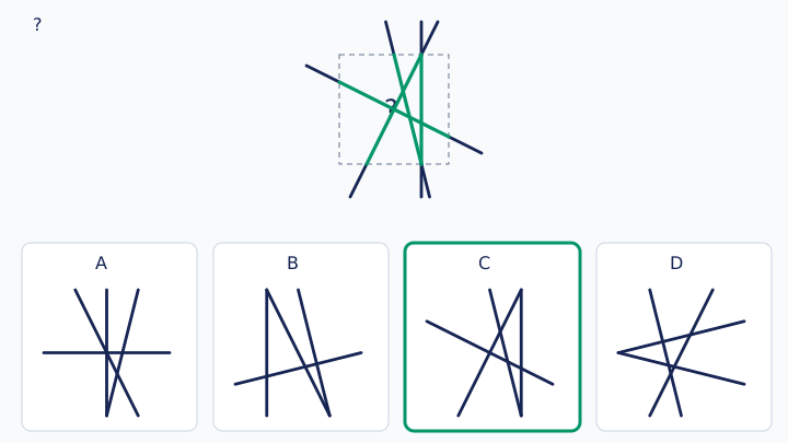
The dashed central square hides parts of straight strokes. Continue each visible stroke straight through the gap, with no extra strokes. Which upright tile completes the figure? Crossings do not mean that a stroke turns.
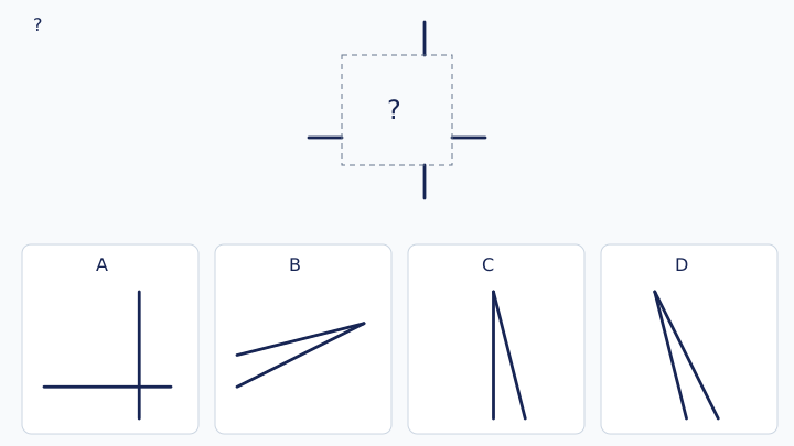
A: Figure A · B: Figure B · C: Figure C · D: Figure D
Practice 25
The dashed central square hides parts of straight strokes. Continue each visible stroke straight through the gap, with no extra strokes. Which upright tile completes the figure? Crossings do not mean that a stroke turns.
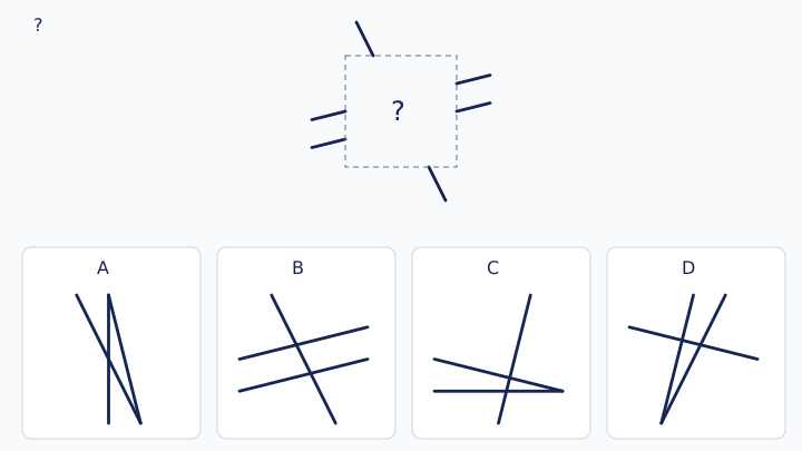
A: Figure A · B: Figure B · C: Figure C · D: Figure D
Practice 26
The dashed central square hides parts of straight strokes. Continue each visible stroke straight through the gap, with no extra strokes. Which upright tile completes the figure? Crossings do not mean that a stroke turns.
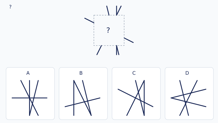
A: Figure A · B: Figure B · C: Figure C · D: Figure D
Practice 27
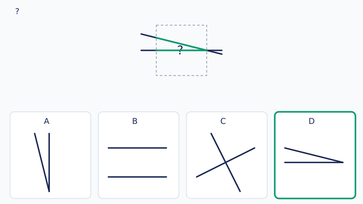
The dashed central square hides parts of straight strokes. Continue each visible stroke straight through the gap, with no extra strokes. Which upright tile completes the figure? Crossings do not mean that a stroke turns.
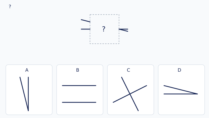
A: Figure A · B: Figure B · C: Figure C · D: Figure D
Practice 28
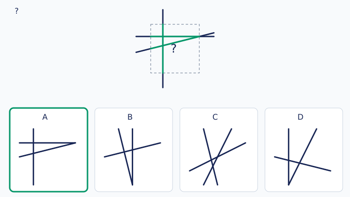
The dashed central square hides parts of straight strokes. Continue each visible stroke straight through the gap, with no extra strokes. Which upright tile completes the figure? Crossings do not mean that a stroke turns.
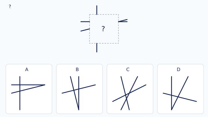
A: Figure A · B: Figure B · C: Figure C · D: Figure D
Practice 29
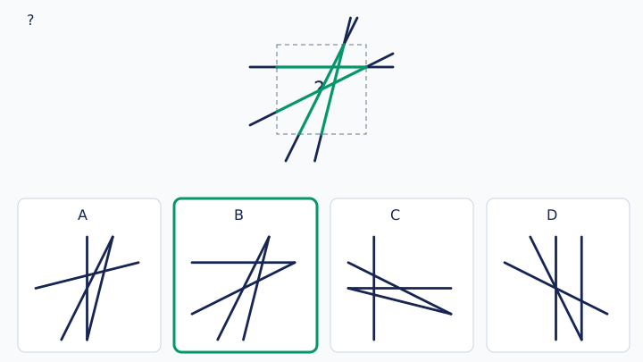
The dashed central square hides parts of straight strokes. Continue each visible stroke straight through the gap, with no extra strokes. Which upright tile completes the figure? Crossings do not mean that a stroke turns.
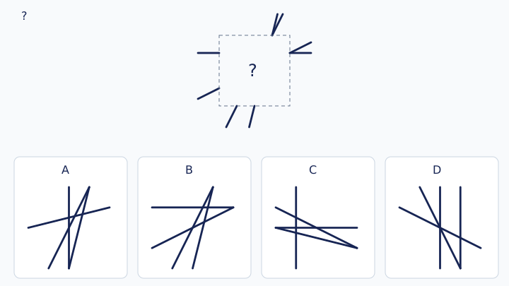
A: Figure A · B: Figure B · C: Figure C · D: Figure D
Practice 30
The dashed central square hides parts of straight strokes. Continue each visible stroke straight through the gap, with no extra strokes. Which upright tile completes the figure? Crossings do not mean that a stroke turns.
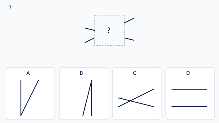
A: Figure A · B: Figure B · C: Figure C · D: Figure D
16. Answers and visual explanations
Answer 01
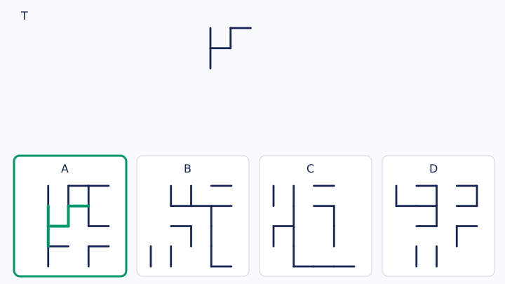
A — Figure A contains the entire target. Use a bend or branch as the anchor, then trace every connected stroke. On a unit grid with the option’s drawing-grid top-left as (0,0), x rightward and y downward, the matching strokes are: (1, 1)–(1, 2); (1, 2)–(1, 3); (1, 2)–(2, 2); (2, 1)–(2, 2); (2, 1)–(3, 1). The green answer overlay shows these strokes; the other options fail the complete-stroke test.
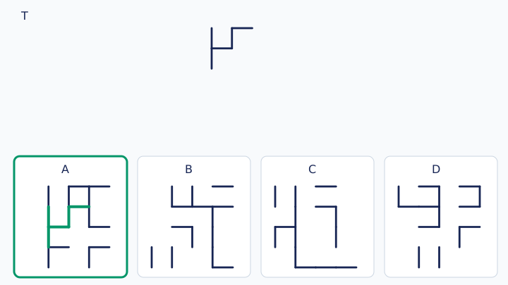
Answer 02
B — Figure B contains the entire target. Use a bend or branch as the anchor, then trace every connected stroke. On a unit grid with the option’s drawing-grid top-left as (0,0), x rightward and y downward, the matching strokes are: (0, 1)–(0, 2); (0, 2)–(0, 3); (0, 2)–(1, 2); (0, 3)–(1, 3); (1, 3)–(2, 3); (2, 2)–(2, 3). The green answer overlay shows these strokes; the other options fail the complete-stroke test.
Answer 03
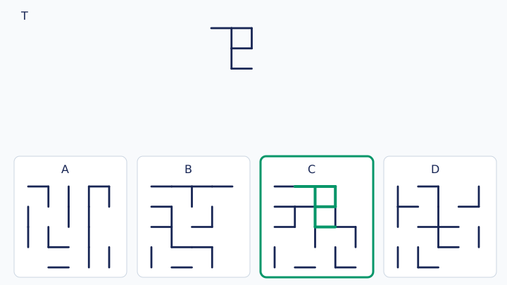
C — Figure C contains the entire target. Use a bend or branch as the anchor, then trace every connected stroke. On a unit grid with the option’s drawing-grid top-left as (0,0), x rightward and y downward, the matching strokes are: (1, 0)–(2, 0); (2, 0)–(2, 1); (2, 0)–(3, 0); (2, 1)–(2, 2); (2, 1)–(3, 1); (2, 2)–(3, 2); (3, 0)–(3, 1). The green answer overlay shows these strokes; the other options fail the complete-stroke test.
Answer 04
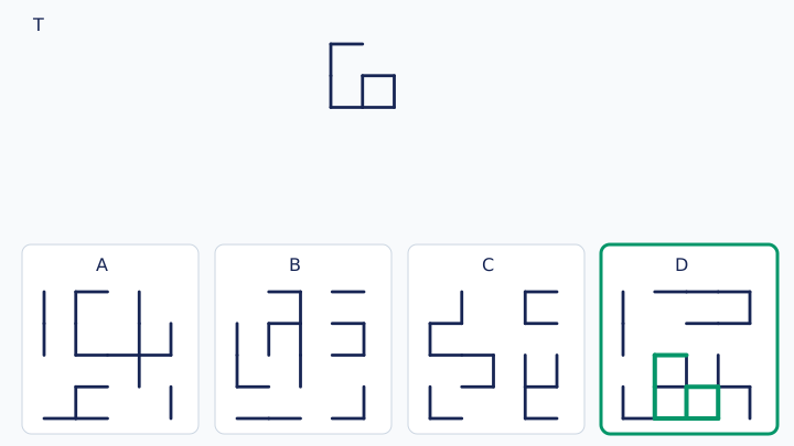
D — Figure D contains the entire target. Use a bend or branch as the anchor, then trace every connected stroke. On a unit grid with the option’s drawing-grid top-left as (0,0), x rightward and y downward, the matching strokes are: (1, 2)–(1, 3); (1, 2)–(2, 2); (1, 3)–(1, 4); (1, 4)–(2, 4); (2, 3)–(2, 4); (2, 3)–(3, 3); (2, 4)–(3, 4); (3, 3)–(3, 4). The green answer overlay shows these strokes; the other options fail the complete-stroke test.
Answer 05
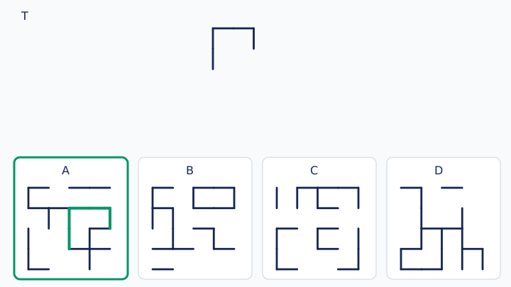
A — Figure A contains the entire target. Use a bend or branch as the anchor, then trace every connected stroke. On a unit grid with the option’s drawing-grid top-left as (0,0), x rightward and y downward, the matching strokes are: (2, 1)–(2, 2); (2, 1)–(3, 1); (2, 2)–(2, 3); (3, 1)–(4, 1); (4, 1)–(4, 2). The green answer overlay shows these strokes; the other options fail the complete-stroke test.
Answer 06
B — Figure B contains the entire target. Use a bend or branch as the anchor, then trace every connected stroke. On a unit grid with the option’s drawing-grid top-left as (0,0), x rightward and y downward, the matching strokes are: (1, 3)–(1, 4); (1, 3)–(2, 3); (2, 2)–(2, 3); (2, 2)–(3, 2); (3, 2)–(3, 3); (3, 3)–(3, 4). The green answer overlay shows these strokes; the other options fail the complete-stroke test.
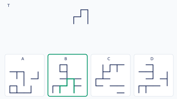
Answer 07
C — Figure C contains the entire target. Use a bend or branch as the anchor, then trace every connected stroke. On a unit grid with the option’s drawing-grid top-left as (0,0), x rightward and y downward, the matching strokes are: (0, 0)–(0, 1); (0, 0)–(1, 0); (0, 1)–(0, 2); (0, 1)–(1, 1); (1, 0)–(1, 1); (1, 1)–(1, 2); (1, 1)–(2, 1). The green answer overlay shows these strokes; the other options fail the complete-stroke test.
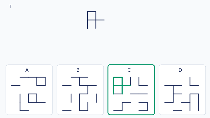
Answer 08
D — Figure D contains the entire target. Use a bend or branch as the anchor, then trace every connected stroke. On a unit grid with the option’s drawing-grid top-left as (0,0), x rightward and y downward, the matching strokes are: (1, 1)–(2, 1); (1, 2)–(1, 3); (1, 3)–(2, 3); (2, 1)–(2, 2); (2, 1)–(3, 1); (2, 2)–(2, 3); (2, 2)–(3, 2); (3, 1)–(3, 2). The green answer overlay shows these strokes; the other options fail the complete-stroke test.
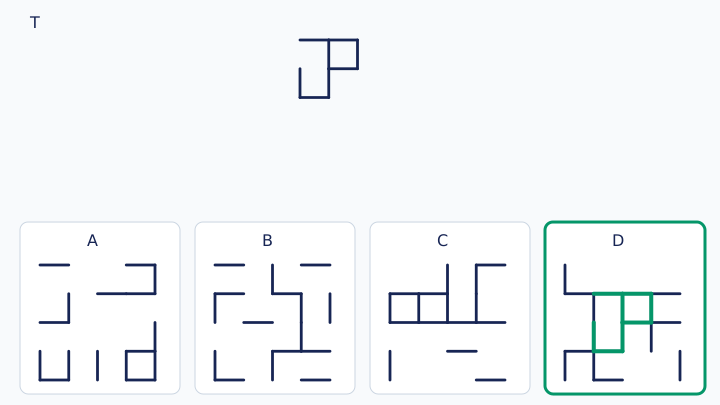
Answer 09
A — Figure A contains the entire target. Use a bend or branch as the anchor, then trace every connected stroke. On a unit grid with the option’s drawing-grid top-left as (0,0), x rightward and y downward, the matching strokes are: (2, 2)–(2, 3); (2, 2)–(3, 2); (3, 2)–(3, 3); (3, 3)–(4, 3); (4, 2)–(4, 3). The green answer overlay shows these strokes; the other options fail the complete-stroke test.
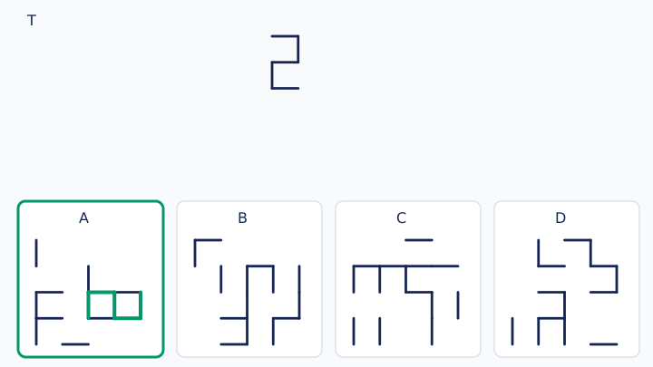
Answer 10
B — Figure B contains the entire target. Use a bend or branch as the anchor, then trace every connected stroke. On a unit grid with the option’s drawing-grid top-left as (0,0), x rightward and y downward, the matching strokes are: (1, 2)–(1, 3); (1, 2)–(2, 2); (1, 3)–(1, 4); (1, 4)–(2, 4); (2, 2)–(3, 2); (3, 2)–(3, 3). The green answer overlay shows these strokes; the other options fail the complete-stroke test.
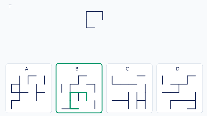
Answer 11
C — Figure C contains the entire target. Use a bend or branch as the anchor, then trace every connected stroke. On a unit grid with the option’s drawing-grid top-left as (0,0), x rightward and y downward, the matching strokes are: (0, 2)–(0, 3); (0, 2)–(1, 2); (0, 3)–(0, 4); (0, 3)–(1, 3); (0, 4)–(1, 4); (1, 2)–(2, 2); (1, 4)–(2, 4). The green answer overlay shows these strokes; the other options fail the complete-stroke test.
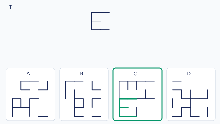
Answer 12
D — Figure D contains the entire target. Use a bend or branch as the anchor, then trace every connected stroke. On a unit grid with the option’s drawing-grid top-left as (0,0), x rightward and y downward, the matching strokes are: (2, 3)–(2, 4); (2, 3)–(3, 3); (2, 4)–(3, 4); (3, 2)–(3, 3); (3, 2)–(4, 2); (3, 3)–(3, 4); (3, 4)–(4, 4); (4, 3)–(4, 4). The green answer overlay shows these strokes; the other options fail the complete-stroke test.
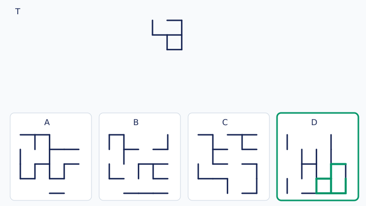
Answer 13
A — Figure A contains the entire target. Use a bend or branch as the anchor, then trace every connected stroke. On a unit grid with the option’s drawing-grid top-left as (0,0), x rightward and y downward, the matching strokes are: (0, 1)–(1, 1); (1, 1)–(2, 1); (1, 3)–(2, 3); (2, 1)–(2, 2); (2, 2)–(2, 3). The green answer overlay shows these strokes; the other options fail the complete-stroke test.
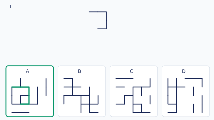
Answer 14
B — Figure B contains the entire target. Use a bend or branch as the anchor, then trace every connected stroke. On a unit grid with the option’s drawing-grid top-left as (0,0), x rightward and y downward, the matching strokes are: (0, 2)–(0, 3); (0, 3)–(0, 4); (0, 3)–(1, 3); (1, 2)–(2, 2); (1, 3)–(2, 3); (2, 2)–(2, 3). The green answer overlay shows these strokes; the other options fail the complete-stroke test.
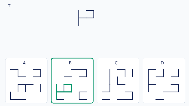
Answer 15
C — Figure C contains the entire target. Use a bend or branch as the anchor, then trace every connected stroke. On a unit grid with the option’s drawing-grid top-left as (0,0), x rightward and y downward, the matching strokes are: (1, 2)–(1, 3); (1, 3)–(2, 3); (2, 2)–(2, 3); (2, 2)–(3, 2); (2, 3)–(3, 3); (3, 1)–(3, 2); (3, 2)–(3, 3). The green answer overlay shows these strokes; the other options fail the complete-stroke test.
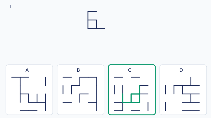
Answer 16
D — Figure D contains the entire target. Use a bend or branch as the anchor, then trace every connected stroke. On a unit grid with the option’s drawing-grid top-left as (0,0), x rightward and y downward, the matching strokes are: (1, 0)–(1, 1); (1, 0)–(2, 0); (1, 1)–(1, 2); (1, 1)–(2, 1); (2, 0)–(3, 0); (2, 1)–(3, 1); (3, 0)–(3, 1); (3, 1)–(3, 2). The green answer overlay shows these strokes; the other options fail the complete-stroke test.
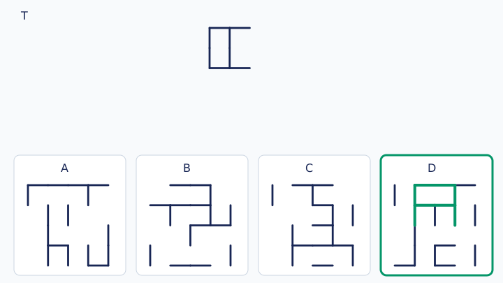
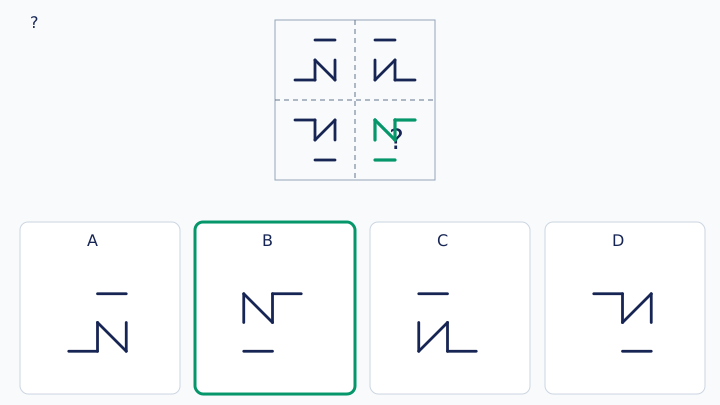
Answer 17
A — Figure A is the reflection of the bottom-left tile across the vertical centre line and of the top-right tile across the horizontal centre line. Equivalently, rotate the top-left pattern by 180°. Check every endpoint against BOTH axes; one-axis symmetry alone is insufficient.
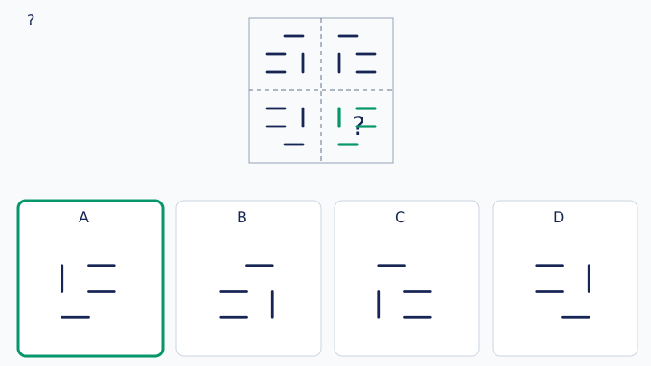
Answer 18
B — Figure B is the reflection of the bottom-left tile across the vertical centre line and of the top-right tile across the horizontal centre line. Equivalently, rotate the top-left pattern by 180°. Check every endpoint against BOTH axes; one-axis symmetry alone is insufficient.
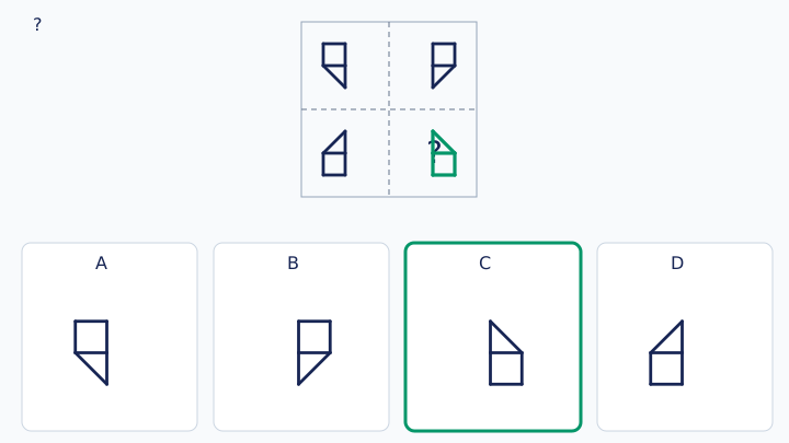
Answer 19
C — Figure C is the reflection of the bottom-left tile across the vertical centre line and of the top-right tile across the horizontal centre line. Equivalently, rotate the top-left pattern by 180°. Check every endpoint against BOTH axes; one-axis symmetry alone is insufficient.
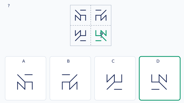
Answer 20
D — Figure D is the reflection of the bottom-left tile across the vertical centre line and of the top-right tile across the horizontal centre line. Equivalently, rotate the top-left pattern by 180°. Check every endpoint against BOTH axes; one-axis symmetry alone is insufficient.
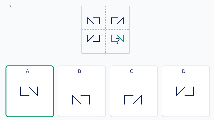
Answer 21
A — Figure A is the reflection of the bottom-left tile across the vertical centre line and of the top-right tile across the horizontal centre line. Equivalently, rotate the top-left pattern by 180°. Check every endpoint against BOTH axes; one-axis symmetry alone is insufficient.
Answer 22
B — Figure B is the reflection of the bottom-left tile across the vertical centre line and of the top-right tile across the horizontal centre line. Equivalently, rotate the top-left pattern by 180°. Check every endpoint against BOTH axes; one-axis symmetry alone is insufficient.
Answer 23
C — Figure C is the reflection of the bottom-left tile across the vertical centre line and of the top-right tile across the horizontal centre line. Equivalently, rotate the top-left pattern by 180°. Check every endpoint against BOTH axes; one-axis symmetry alone is insufficient.
Answer 24
A — Figure A preserves the entry point, exit point and slope of every straight stroke. Matching the number of lines alone is insufficient. Extend each outside stub along its own direction; their required segments are [((0, 3), (4, 3)), ((3, 0), (3, 4))], in local coordinates from 0 to 4 (x right, y down).
Answer 25
B — Figure B preserves the entry point, exit point and slope of every straight stroke. Matching the number of lines alone is insufficient. Extend each outside stub along its own direction; their required segments are [((0, 2), (4, 1)), ((0, 3), (4, 2)), ((1, 0), (3, 4))], in local coordinates from 0 to 4 (x right, y down).
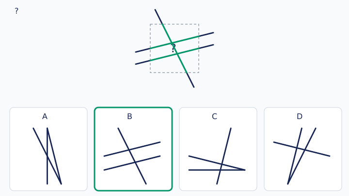
Answer 26
C — Figure C preserves the entry point, exit point and slope of every straight stroke. Matching the number of lines alone is insufficient. Extend each outside stub along its own direction; their required segments are [((0, 1), (4, 3)), ((1, 4), (3, 0)), ((2, 0), (3, 4)), ((3, 0), (3, 4))], in local coordinates from 0 to 4 (x right, y down).
Answer 27
D — Figure D preserves the entry point, exit point and slope of every straight stroke. Matching the number of lines alone is insufficient. Extend each outside stub along its own direction; their required segments are [((0, 1), (4, 2)), ((0, 2), (4, 2))], in local coordinates from 0 to 4 (x right, y down).
Answer 28
A — Figure A preserves the entry point, exit point and slope of every straight stroke. Matching the number of lines alone is insufficient. Extend each outside stub along its own direction; their required segments are [((0, 1), (4, 1)), ((0, 2), (4, 1)), ((1, 0), (1, 4))], in local coordinates from 0 to 4 (x right, y down).
Answer 29
B — Figure B preserves the entry point, exit point and slope of every straight stroke. Matching the number of lines alone is insufficient. Extend each outside stub along its own direction; their required segments are [((0, 1), (4, 1)), ((0, 3), (4, 1)), ((1, 4), (3, 0)), ((2, 4), (3, 0))], in local coordinates from 0 to 4 (x right, y down).
Answer 30
C — Figure C preserves the entry point, exit point and slope of every straight stroke. Matching the number of lines alone is insufficient. Extend each outside stub along its own direction; their required segments are [((0, 2), (4, 3)), ((0, 3), (4, 1))], in local coordinates from 0 to 4 (x right, y down).
This is AI-generated information.